


1. Introduction
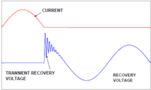
Transient Recovery Voltage (TRV) is the voltage that appears across the terminals of a pole of a circuit-breaker after interruption of a current. This voltage may be considered in two successive time intervals: one during which a transient voltage exists, followed by a second one during which a power frequency voltage alone exists.
Circuit breakers can fail to interrupt fault currents when the TRV characteristics exceed the rating of the circuit breaker. Understanding and managing TRV is therefore critical for the reliable protection of power systems.
2. Origin of Transient Recovery Voltage
When a circuit breaker interrupts a current, the arc between its contacts is extinguished at a natural current zero. At this moment, the energy stored in the inductances and capacitances of the network is redistributed, generating a transient oscillatory voltage across the breaker terminals.
The shape and magnitude of this TRV depend on several factors:
- The type of fault (three-phase, phase-to-phase, phase-to-earth)
- The network configuration and topology
- The location of the fault relative to the circuit breaker
- The impedances (inductive and capacitive) of the network elements
3. TRV Waveform and Key Parameters
The TRV waveform is typically characterized by the following parameters as defined in IEC 62271-100:
- Peak voltage (uc): the maximum voltage reached during the transient phase
- Rate of Rise of Recovery Voltage (RRRV): the initial rate at which the TRV rises, expressed in kV/µs. A high RRRV is particularly stressful for the circuit breaker’s interrupting capability
- Time to peak (t3): the time required to reach the peak TRV voltage
- Time delay (td): a short time interval at the beginning of TRV during which the voltage rise is delayed due to stray capacitances near the circuit breaker
The TRV envelope is often represented by a two-parameter (for distribution systems) or four-parameter (for transmission systems) reference line defined in IEC and IEEE standards.
4. Effect of TRV on Circuit Breaker Performance
The interrupting capability of a circuit breaker is directly affected by the TRV. If the rate of rise or the peak value of the TRV exceeds the withstand capability of the breaker, re-ignition of the arc may occur, leading to:
- Failure to interrupt the fault current
- Prolonged fault duration, increasing equipment damage
- Potential catastrophic failure of the circuit breaker itself
This is why circuit breakers are tested and rated against defined TRV envelopes during type testing according to IEC 62271-100 and IEEE C37.09 standards.
5. Special TRV Conditions
Certain network configurations generate particularly severe TRV conditions:
- Terminal faults: faults occurring at or very close to the circuit breaker terminals produce the highest RRRV values
- Short-line faults (SLF): faults occurring a few kilometers from the breaker on overhead transmission lines generate a very steep initial TRV rise due to traveling wave phenomena on the line. SLF conditions are among the most demanding for high-voltage circuit breakers
- Out-of-phase switching: when two parts of a network that are out of phase are connected or disconnected, the TRV can reach up to twice the normal system voltage
- Capacitive and inductive load switching: interruption of small inductive currents (transformers at no-load, reactors) or capacitive currents (cables, capacitor banks) can also generate severe TRV due to the energy stored in the reactive elements
6. TRV Mitigation Measures
When the TRV requirements exceed the standard rating of available circuit breakers, several mitigation techniques can be applied:
- Surge capacitors: capacitors installed at the circuit breaker terminals reduce the RRRV by increasing the local capacitance, slowing down the initial voltage rise
- Surge arresters: metal oxide surge arresters limit the peak TRV voltage
- Pre-insertion resistors: resistors temporarily inserted during the opening operation to damp the transient oscillations
- Upgrading the circuit breaker: selecting a breaker with a higher TRV withstand capability (e.g., moving from a standard-duty to a special-duty breaker)
- Network reconfiguration: modifying the substation layout or adding bus-tie reactors to reduce the severity of TRV at the breaker location
7. TRV Studies and Engineering Practice
TRV analysis is an integral part of power system protection studies, particularly for high-voltage and extra-high-voltage substations. The study typically involves:
- Electromagnetic transient simulations using tools such as EMTP-RV, PSCAD, or ATP-EMTP
- Modeling of the network topology, transformers, cables, overhead lines, and substation capacitances
- Computation of TRV envelopes for various fault types and locations
- Comparison with circuit breaker TRV ratings as per IEC 62271-100 or IEEE C37.06
- Recommendation of mitigation measures if required
At Ynni Consulting, we carry out TRV studies as part of our comprehensive power system engineering services, ensuring that circuit breakers are correctly rated and that protection systems operate reliably under all network conditions.
8. Conclusion
Transient Recovery Voltage is a fundamental parameter governing the ability of a circuit breaker to successfully interrupt fault currents. Underestimating TRV severity can lead to breaker failure and significant damage to the power system. Rigorous TRV analysis, based on electromagnetic transient simulations and compliance with IEC/IEEE standards, is essential for the safe design and operation of any high-voltage installation.